Build your own board
picogame can run on a board you wire yourself, as long as it has an SPI display, a few buttons - and a firmware build with the picogame module (prebuilt for the boards on Supported hardware, or your own build). This page takes a bare Raspberry Pi Pico (or Pico W / Pico 2) plus a display and gets a game running on it.
Wire it
Section titled “Wire it”This is the PicoPad’s pin map. Matching it requires the least configuration, but you can choose
other suitable GPIO pins and name them in settings.toml. Schematics: Pajenicko PicoPad
hardware.
| Function | Pico GPIO | Notes |
|---|---|---|
| Display SCK | GP18 | SPI clock |
| Display MOSI | GP19 | SPI data (to display SDA/DIN) |
| Display DC | GP17 | data/command |
| Display CS | GP21 | chip select |
| Display RST | GP20 | reset |
| Display BL | GP16 | backlight (tie high, or PWM to dim) |
| ↑ Up | GP4 | button to GND (active-low, internal pull-up) |
| ↓ Down | GP5 | |
| ← Left | GP3 | |
| → Right | GP2 | |
| A | GP7 | |
| B | GP6 | |
| X / Y (optional) | GP9 / GP8 | |
| Speaker | GP15 | PWM audio, through a small transistor/amp or a piezo |
| Display VCC / GND | 3V3 / GND | also the common for buttons & speaker |
Buttons wire to GND (read active-low with an internal pull-up). The ST7789 bus runs up to
62.5 MHz. On a breadboard keep the display wires short, or drop PICOGAME_BAUD (below).
Three ways to give the engine a display
Section titled “Three ways to give the engine a display”A game asks for the screen through picogame_game.screen() / picogame_game.display(). Those read
supervisor.runtime.display — the board’s primary display, which CircuitPython sets when the
firmware builds one, and which a boot.py or a launcher publishes itself. That is the only way a
display reaches a game (the simulator and the browser playground ship a small supervisor shim of
their own), so the job here is to build the display once and publish it. Pick one path:
- Your board already has
board.DISPLAY(PicoPad, PicoSystem, µGame, Thumby, VIDI X). Nothing to do: copy your game ascode.pyplus thelib/it imports. Done. - A picogame custom-board firmware: the Pico / Pico W / Pico 2 / Pico 2 W
downloads expose a
board.DISPLAYslot. A smallboot.pybuilds the display fromsettings.toml, and your game remains unchanged ascode.py. This also works for existing games andstage-based games. After copyingboot.py, press RESET once (or unplug/replug USB):boot.pyruns only at power-on — a save/soft-reload runscode.pybut notboot.py, so until that reset there is no display and a game dies withRuntimeError: no display: if you just added boot.py press RESET once …— the message names the fix. - A stock / other firmware (no slot). A launcher
code.pybuilds the display, publishes it withsupervisor.runtime.display = disp, then runs your game (asgame.py). A little more setup.
Grab the ready boot.py / launcher from
custom_board/ in the repo. Each
path has its own folder; use one. The display driver is Python (an init table inside the file), so
adding a new controller needs no firmware rebuild.
Configure it — one settings.toml
Section titled “Configure it — one settings.toml”Both non-native paths (and the game itself) read the same settings.toml. One file describes the
whole board:
# DisplayPICOGAME_DISPLAY = "st7789"        # or "ili9341"PICOGAME_PINS    = "SCK=GP18 MOSI=GP19 DC=GP17 CS=GP21 RST=GP20 BL=GP16"PICOGAME_SIZE    = "320x240"       # WIDTH x HEIGHT; WIDTH > HEIGHT = landscapePICOGAME_FLIP    = ""              # "", "h", "v", "hv" — orientation (see below)PICOGAME_INVERT  = 0               # colours negative? -> 1PICOGAME_BGR     = 0               # red/blue swapped? -> 1PICOGAME_BAUD    = 24000000        # lower on long breadboard wires
# Buttons (active-low, to GND) — token is LOGICAL=GPpinPICOGAME_BUTTONS = "UP=GP4 DOWN=GP5 LEFT=GP3 RIGHT=GP2 A=GP7 B=GP6 X=GP9 Y=GP8"
# Audio (optional)PICOGAME_AUDIO   = "GP15"          # PWM speaker pin; omit if none
Re-wiring a button is then a one-character edit, no code. (The launcher path also reads
PICOGAME_GAME = "game" to know which module to run.)
Full settings.toml reference
Section titled “Full settings.toml reference”The keys above cover the common case. Below is every runtime key picogame reads. All are read at
runtime, so a board is adapted with no reflash — a key takes effect on the next reload (display keys
need a full restart, see the note above). os.getenv hands every value back as a string, so write
on/off as 1/0 and keep volumes to whole dB; picogame parses nothing fancier.
| Key | Format / values | Example | Note |
|---|---|---|---|
PICOGAME_PULL |
"up" or "down" |
PICOGAME_PULL = "up" |
Internal resistor + active level for all buttons. up = wired to GND, pressed reads low (default); down = wired to 3V3, pressed reads high. |
PICOGAME_MATRIX_ROWS |
space/comma GP pins | "GP0 GP1 GP2 GP3" |
Row pins of a scanned key matrix (see intro below). |
PICOGAME_MATRIX_COLS |
space/comma GP pins | "GP4 GP5 GP6 GP7" |
Column pins of the matrix. |
PICOGAME_MATRIX_MAP |
NAME=row,col tokens |
"UP=1,2 A=3,5 START=0,0" |
Maps matrix cells to game buttons. Also accepts NAME=key_number (key = row*ncols+col). Map only the keys you want; the rest are ignored. |
PICOGAME_MATRIX_ANODES |
"cols" or "rows" |
"cols" |
Optional; which axis is driven. Default cols; flip to rows if the diode direction is reversed. |
PICOGAME_AUDIO_OUT |
"headphone" / "speaker" / "both" |
"headphone" |
Output select for an I2S DAC (Fruit Jam TLV320). Default headphone. |
PICOGAME_HP_VOLUME |
integer dB, <= 0 |
-10 |
Headphone analog trim. 0 = line level (too loud for earbuds — stay <= -3); -78 = silent. With the key unset the lib applies -10. |
PICOGAME_DAC_VOLUME |
integer dB, <= 0 |
-3 |
Main digital fader. Keep <= 0 to avoid DSP clipping. |
PICOGAME_SPK_VOLUME |
integer dB, <= 0 |
-10 |
Speaker analog trim (same scale as headphone). |
PICOGAME_USB |
1 / 0 |
PICOGAME_USB = 0 |
On a USB-host build, 0 disables auto-attach of USB HID input (gamepad + keyboard). Default on. |
PICOGAME_KBD |
1 / 0 |
PICOGAME_KBD = 0 |
0 disables the USB keyboard only (the gamepad still auto-attaches). Default on. |
PICOGAME_USBPAD |
NAME=byte:bitmask tokens |
"A=5:0x40 B=5:0x20" |
Remap gamepad buttons (HID report byte index : bitmask). A partial list merges over the DragonRise defaults. |
PICOGAME_USBPAD_ID |
"VID:PID" (hex) |
"081f:e401" |
The pad’s USB VID/PID. Required for any pad that is not the DragonRise 081f:e401 default — the driver matches by VID/PID and never grabs “the first device”, so without this key another pad simply isn’t found. A truly custom pad also needs its byte map via PICOGAME_USBPAD. |
PICOGAME_USBPAD_TIMEOUT |
ms | 10 |
HID read timeout for the gamepad poll. Raise only if a pad drops inputs. |
PICOGAME_USBKBD |
NAME=keycode tokens |
"A=0x2C START=0x28" |
Remap USB-keyboard keys to game buttons (HID keycode, hex or decimal). Merges over the default arrows/WASD layout. |
PICOGAME_USBKBD_EP |
"iface:endpoint" |
"2:0x83" |
Point the keyboard driver at the live interface/IN-endpoint of a combo dongle whose boot interface is silent (find it with tools/usbkbd_probe.py). |
PICOGAME_USBKBD_TIMEOUT |
ms | 10 |
HID read timeout for the keyboard poll. |
PICOGAME_I2CPAD |
preset / recipe | "qwstpad" |
Opt-in I2C gamepad (GPIO-expander pads, e.g. Pimoroni QwSTPad) — works on any board with I2C, no USB host needed. A preset name, preset@0xNN, several separated by ;, or a full recipe ("addr=0x20 read=:1 inv=1 UP=0 A=4 …"). Off unless set. |
PICOGAME_I2C |
"SDA,SCL" pins, or a bus name |
"GP4,GP5" |
I2C bus for the pad above. Only needed on a bare board or non-standard wiring — a STEMMA/Qw-ST connector needs nothing. A single token names a board bus instead ("I2C0"). |
PICOGAME_SHIFTPAD |
preset / recipe | "pybadge" |
Opt-in buttons behind a 74HC165 shift register (PyBadge and friends). A preset name, or a full recipe ("latch=… clock=… data=… bits=8 A=1 B=0 …"). Off unless set — clocking three unknown GPIOs is never probed. |
PICOGAME_TILTPAD |
preset / recipe | "pybadge" |
Opt-in accelerometer as a D-pad; its directions are OR’ed with the real buttons. A preset, or a preset plus overrides ("lis3dh on=4000 off=2500"). Off unless set. |
PICOGAME_RGB444 |
1 / 0 |
PICOGAME_RGB444 = 1 |
1 sends 12-bit RGB444 to the panel (~25% less SPI traffic) wherever the firmware supports it (picogame.RGB444_SUPPORTED). Worth it on a slow bus (PyBadge: 24 MHz SPI). A game’s explicit setup(rgb444=...) wins over the key. Off unless set. |
PICOGAME_DEBUG |
1 / 0 |
PICOGAME_DEBUG = 1 |
When something doesn’t work, set this. Prints [picogame] ... failure reasons (audio DAC/driver, USB pad/keyboard, …) to the serial console. Remove once working. |
Buttons on a key matrix. If your buttons are wired as a scanned row × column grid (a small
keypad or a QWERTY block) instead of one pin per button, use the PICOGAME_MATRIX_* keys above instead
of PICOGAME_BUTTONS. Map only the cells you care about onto game buttons. Discover each cell’s
(row, col) (or key number) by running matrix_probe.py first — it prints them as you press.
USB gamepad. On a USB-host firmware (Fruit Jam) a pad plugged into the USB-HOST port auto-attaches
with no game change; the default layout is the DragonRise 081f:e401 generic pad. Set PICOGAME_USB = 0
to turn that off, or remap another pad’s buttons with PICOGAME_USBPAD (discover its report bytes with
the USB probe tool).
If the picture is wrong
Section titled “If the picture is wrong”picogame draws straight to the panel, so orientation lives in the panel’s own settings, not in a
software rotation. Toggle these in settings.toml until it looks right, no code:
| Symptom | Fix |
|---|---|
| Sideways / wrong aspect | swap PICOGAME_SIZE (320x240 ↔ 240x320) |
| Upside down | PICOGAME_FLIP = "hv" |
| Mirror image (text backwards) | PICOGAME_FLIP = "h" (or "v" if flipped vertically) |
| Photo-negative colours | flip PICOGAME_INVERT (0 ↔ 1) — ST7789 panels come in both polarities; the key sets the panel’s correct resting state and works on the stock PicoPad firmware too |
| Red/blue swapped or image mirrored on stock PicoPad firmware | PICOGAME_MADCTL = the absolute panel-orientation byte: 0x60 stock · 0x68 BGR panel · 0xA0 mounted 180° · 0xA8 both. (On a DIY board use PICOGAME_BGR/PICOGAME_FLIP above instead.) |
| Backlight too bright / dim by default | PICOGAME_BRIGHTNESS = integer percent 0–100 (applied at game setup) |
| Red and blue swapped | PICOGAME_BGR = 1 |
Panel modules vary. Change one setting at a time and check the result. An ST7789 often uses
INVERT = 1, and an ILI9341 often uses BGR = 1, but the correct value depends on the module.
Check the wiring first: input_example
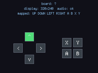
Section titled “Check the wiring first: input_example”Before your game, drop input_example.py (in the repo’s examples/) on the board. It prints what
the engine detected — board id, display size, mapped buttons, audio — to the serial console, and draws
the D-pad + A/B/X/Y as squares that light up and beep as you press them. An unmapped button stays
dark, so a wiring or settings.toml mistake shows at a glance.
Then deploy as usual
Section titled “Then deploy as usual”Once the display and buttons respond, everything else — shipping .mpy, the RAM budget, flashing — is
the same as on the other supported boards: see Run on hardware.